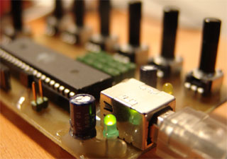
The gnusb hardware
The gnusb is powered by the USB bus. Although most USB ports are short circuit protected, there's a 300mA resettable fuse for added security.
We power the Atmega16 at bus power in order to get 0-5V for our sensors. To be in the USB specification we added zener diodes on the data lines, to keep them at 3.3V.

Two status leds provide feedback on the gnusb operation. The green led is lit when we're in normal operation. The yellow led lights alone if we're in bootloader mode, and it flashes while uploading a new program. You can also use it in you're firmware to provide additional feedback. See gnusb.h in the firmware directory.
Apart for some capacitors to eliminate noise on the power supply and a 12Mhz quartz oscillator, no additional components are needed. The whole circuit fits on a small single sided PCB, or can be easily assembled on a breadboard. There are different proposals for a board layout in the download. I opted for a mixed through hole / surface mount design to keep it small, reduce the number of holes to be drilled, and because I prefer soldering smd components a lot. By the way: SparkFun electronics has some good tutorials on the matter...
Oh, and the analog supply is further decoupled by a LC circuit, to keep it really steady.


